Are you feeling overwhelmed by terms like “thread,” “process connection,” “connector,” and “fitting”?
Not to mention the various regional common standards and specifications to contend with.Interested in finding the best fit for your specific application requirements?
Explore the four primary thread connection types SJ Gauge offers: NPT, PT, G and M.
We will introduce each of these frequently used thread connection types and identify the distinctions between them.You can also contact our professional sales team, and we will do our best to provide you with the most suitable customized measurement solutions for your application.
1. What Are Threads? What Are Their Functions?
Threads, also known as fittings, connectors, and threaded joints, are used to connect pressure gauges to pressure medium sources.
They are composed of external threads (male threads) and internal threads (female threads) that are tightened together.
The primary function of threads is to ensure that pressure or medium can be transmitted to the pressure gauge in a completely sealed condition.
Sometimes, accessories such as sealing tape, O-rings and gaskets are used in conjunction with threads.
Therefore, when selecting thread sizes, it is essential to consider whether they correspond to the specifications of the pressure gauge connector.
When purchasing instruments such as pressure gauges or thermometers, it is also important to provide information about the thread sizes to the supplier.
2. What Problems Can Arise from Choosing the Wrong Thread Connection Type?
What problems can arise from poorly matched thread connections?
Before confirming the thread connection type, refrain from connecting threads to your instruments.
This can potentially lead to equipment damage, production line downtime, and poor production efficiency.
Visual inspection is not sufficient to determine whether the thread connection type is incorrect.
Why is it essential to clarify the thread connection type?
When attempting to connect two different thread types, the threads may not fit securely together due to differences in pitch or diameter.
This can result in the threads not fully tightening. If you attempt to force their installation, it may lead to deformation of the thread crest angles, jamming and immobility of the threads. Even if you eventually manage to remove them from the pipeline, a proper seal cannot be achieved.
All of the above issues can potentially lead to the leakage, contamination or instrument failure of the process measuring medium.
Fortunately, if you can identify the correct connection, you can significantly reduce the occurrence of these problems.
3. Two Measuring Tools to Know Before Selecting Threads
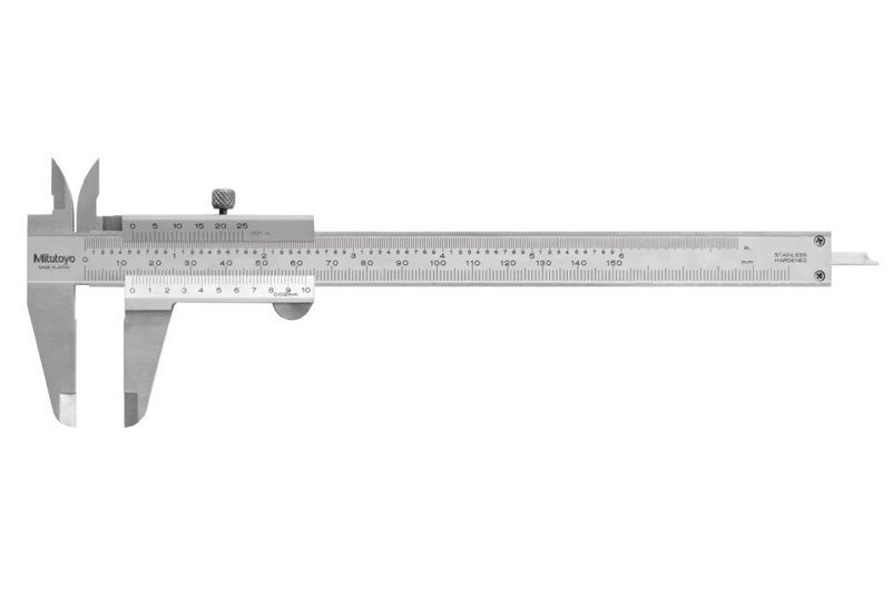
a. Vernier Caliper
A vernier caliper, also known as a vernier scale, vernier gauge or vernier scale caliper, is a common precision measuring tool used for measuring length, inner and outer diameters, and depth. It consists of two parts: the main scale and the vernier scale, which slides along the main scale.
The main scale is typically graduated in millimeters (mm) and comes in different subdivisions, such as ten divisions, twenty divisions or fifty divisions.
Vernier calipers are named accordingly, such as the “ten-division vernier caliper,” “twenty-division vernier caliper,” or “fifty-division vernier caliper.”
Today, there are various styles of vernier calipers. In addition to the traditional form shown in the image below, there are also dial calipers (which can be used in conjunction with a gauge to measure simultaneously) and digital calipers (which display measurement data on an LCD screen).
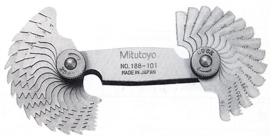
b. Thread Gauge
A Thread Gauge is also known as a screw gauge or pitch gauge.
It is used to assist in measuring thread specifications. You can simply use the thread gauge to repeatedly compare and find the size that fits perfectly.
The most common thread types available in the market are the American Standard, British Standard and Metric systems, each of which has its own specific thread gauge specifications.
4. Identifying Threads in Four Simple Steps
SJ Gauge will guide you through the “Four Steps to Identify Threads Specifications,” and you can select the most suitable thread size by following them:
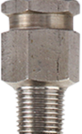
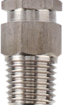
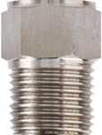
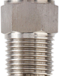
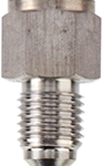
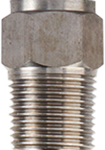
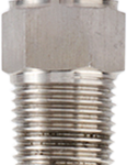
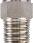
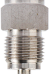
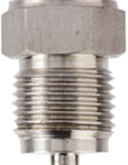
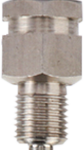
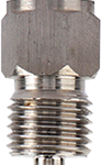
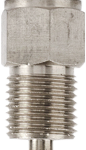
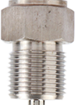
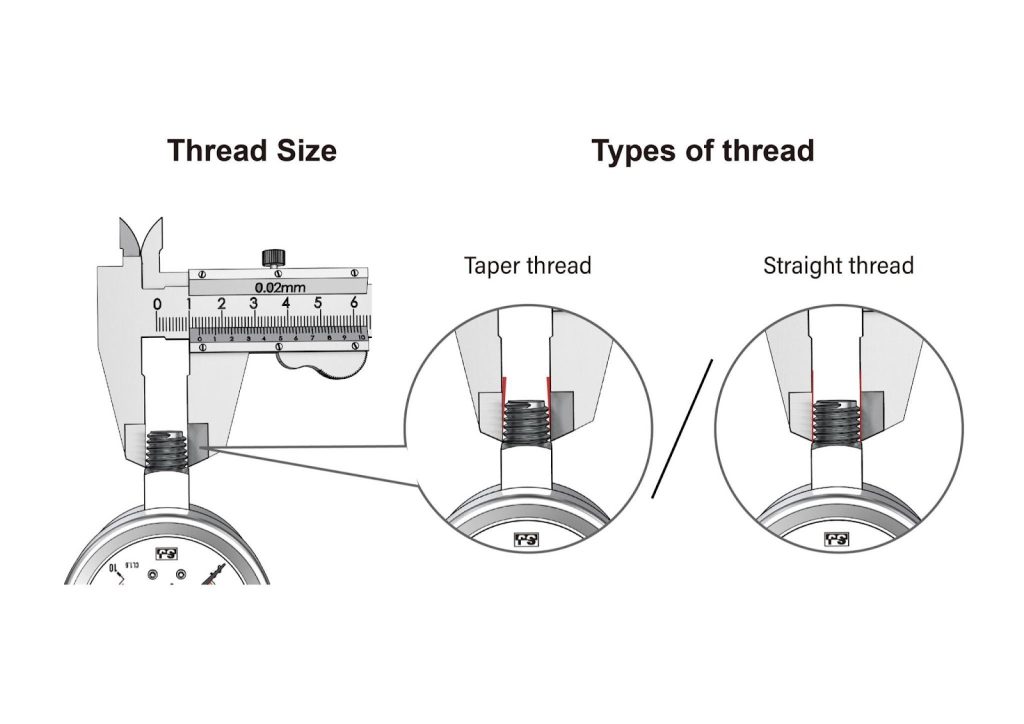
a. Determine If the Thread Is Straight (Parallel) or Tapered (Conical):
If the thread diameter gradually increases or decreases, the thread is tapered; if the diameter remains constant, the thread is straight.
If it is difficult to discern with the naked eye, you can use a vernier caliper for assistance.
Simply clamp the vernier caliper around both ends of the thread and observe.
If both sides form a slight triangular shape, it is tapered; if both sides remain perfectly parallel, it is straight
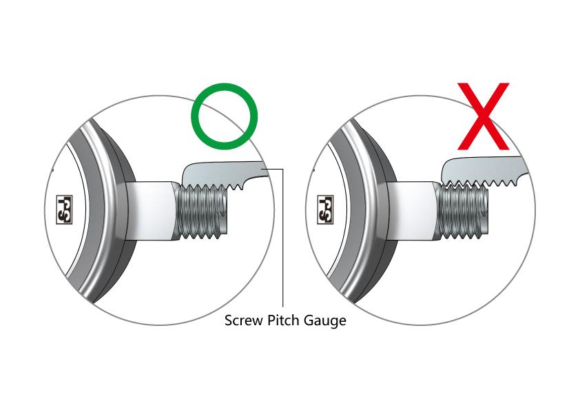
b. Determine the Type of Thread and Pitch
By using the most common American Standard, British Standard and Metric thread gauges, the one that fits the thread most closely is the appropriate thread specification.
There are two methods for expressing thread pitch, mainly divided into Metric and other systems (American Standard and British Standard).
In the Metric system (left image), the measurement is the distance between two adjacent thread crests (e.g., 1.5 mm between two thread crests), while in the American Standard and British Standard systems (right image), the measurement is the number of threads per inch (e.g., 14 thread crests per inch).

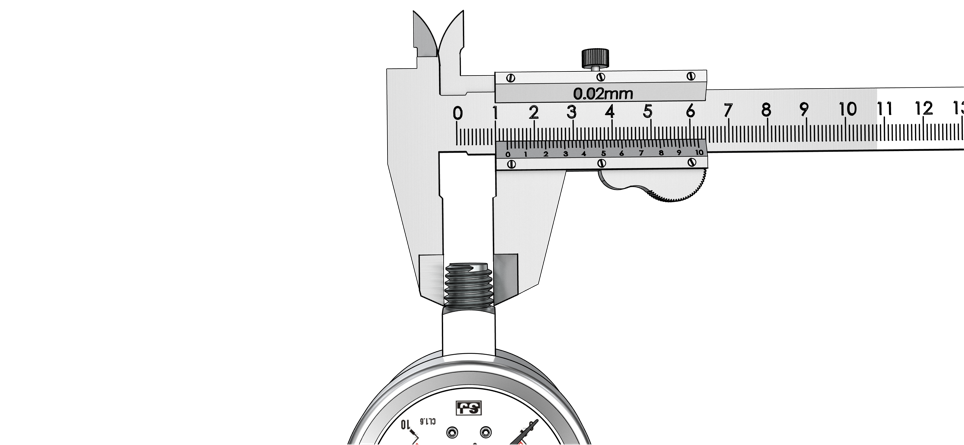
c. Determine the Size of the Connector
By clamping a vernier caliper around both ends of the thread, you can obtain an approximate measurement of the external diameter of the joint.
Next, you can compare this measurement to the closest values in the respective tables to determine the size.
d. Refer to Various Thread Standard Tables (Straight, Taper, Size, Pitch, Size)
You can refer to the information and tables we have compiled below, which compare the most common thread forms, including American Standard, British Standard, and Metric.
American Standard Straight Threads (SAE=UN=UNF)
The most common straight thread form in the United States is UN/UNF (Unified National Fine) threads, also known as SAE (Society of Automotive Engineers)straight threads. The table below lists some common sizes for SAE straight threads.
The naming convention for American Standard straight threads is as follows: Size – Number of Threads per Inch, Type, for example, 3/4-16, UN/UNF.
| American Standard Straight Threads SAE=UN=UNF | |||||
| Size | Threads per inch (TPI) | Thread diameter (mm) | Thread angle | ||
| (inch) | Major diameter | Simple pitch diameter | Minor diameter | ||
| 5/16 | 24 | 7.938 | 7.249 | 6.792 | 60° |
| 7/16 | 20 | 11.113 | 10.287 | 9.738 | |
| 1/2 | 20 | 12.7 | 11.875 | 11.325 | |
| 9/16 | 18 | 14.288 | 13.325 | 12.559 | |
| 3/4 | 16 | 19.05 | 18.019 | 17.331 | |
| 1-1/16 | 12 | 26.988 | 25.613 | 24.695 | |
| 1-5/16 | 12 | 33.338 | 31.963 | 31.046 | |
| Size-TPI, Type e.g. 3/4-16, UN | |||||
American Standard Tapered Threads (NPT / NPTF):
NPT (National Pipe Taper) American Standard Tapered Threads, officially known as American National Standard Taper Pipe Thread, are widely used in the United States for pipe connections.
NPTF American Standard Tapered Threads – Dryseal, also known as the American Standard Pipe Thread Tapered – Dryseal), are not recommended by the National Fluid Power Association (N.F.P.A.), but they are still widely utilized.
The primary difference between NPT threads and NPTF threads is that the NPT does not have a sharp crest, resulting in a small leak point after assembly, requiring the use of sealant for proper sealing.
The naming convention for American Standard Tapered Threads is as follows: Size – Number of Threads per Inch, Type, for example, 1/4-18, NPT.
| American Standard Tapered Threads NPT / NPTF | |||||
| Size | Threads per inch (TPI) | Thread diameter (mm) | Thread angle | ||
| (inch) | Major diameter | Simple pitch diameter | Minor diameter | ||
| 1/16 | 27 | 7.894 | 7.142 | 6.398 | 60° |
| 1/8 | 27 | 10.242 | 9.489 | 8.737 | |
| 1/4 | 18 | 13.616 | 12.487 | 11.358 | |
| 3/8 | 18 | 17.055 | 15.926 | 14.797 | |
| 1/2 | 14 | 21.224 | 19.772 | 18.321 | |
| 3/4 | 14 | 26.569 | 25.117 | 23.666 | |
| 1 | 11.5 | 33.228 | 31.461 | 29.694 | |
| 1-1/4 | 11.5 | 41.985 | 40.218 | 38.454 | |
| 1-1/2 | 11 | 48.054 | 46.287 | 44.52 | |
| 2 | 11 | 60.092 | 58.325 | 56.558 | |
| Size-TPI, Type e.g. 1/4-18, NPT | |||||
British Standard Parallel Threads (BSPP=BSP=PF=G):
These threads adhere to standards set by the British Standards Institution (BSI). British Standard Parallel Threads are commonly referred to using one of four terms: G Thread, BSPP (British Standard Pipe Parallel), BSPM, or BSP.
BSPF (British Standard Pipe Fitting) is the former term used for British Standard Parallel Threads. It was introduced to resolve confusion between BSPP (British Standard Pipe Parallel) and BSPT (British Standard Tapered Threads) regarding pronunciation.
The naming convention for British Standard Parallel Threads is as follows: G Size – Number of Threads per Inch, for example, G 1/8-28.
| British Standard Parallel Threads BSPP=BSP=PF=G | |||||
| Size | Threads per inch (TPI) | Thread diameter (mm) | Thread angle | ||
| (inch) | Major diameter | Simple pitch diameter | Minor diameter | ||
| 1/16 | 28 | 7.732 | 7.142 | 6.561 | 55° |
| 1/8 | 28 | 9.782 | 9.147 | 8.566 | |
| 1/4 | 19 | 13.157 | 12.301 | 11.455 | |
| 3/8 | 19 | 16.662 | 15.806 | 14.95 | |
| 1/2 | 14 | 20.955 | 19.793 | 18.631 | |
| 5/8 | 14 | 22.911 | 21.749 | 20.587 | |
| 3/4 | 14 | 26.441 | 25.279 | 24.117 | |
| 7/8 | 14 | 30.201 | 29.039 | 27.877 | |
| 1 | 11 | 33.249 | 31.77 | 30.291 | |
| 1-1/8 | 11 | 37.897 | 36.418 | 34.939 | |
| 1-1/4 | 11 | 41.91 | 40.431 | 38.952 | |
| 1-1/2 | 11 | 47.803 | 46.324 | 44.845 | |
| 1-3/4 | 11 | 53.746 | 52.267 | 50.788 | |
| 2 | 11 | 59.614 | 58.135 | 56.656 | |
| G Size-TPI e.g. G 1/8-28 | |||||
British Standard Tapered Threads (BSPT=PT=R=RC=ZG):
British Standard Tapered Threads are commonly known as BSPT (The British Standard Pipe Taper), although the term “R Thread” has now replaced it. However, BSPT remains one of the widely accepted terms.
The naming convention for British Standard Tapered Threads is as follows: R Size – Number of Threads per Inch, for example, R 1/2-14.
| British Standard Tapered Threads BSPT=PT=R=RC=ZG | |||||
| Size | Threads per inch (TPI) | Thread diameter (mm) | Thread angle | ||
| (inch) | Major diameter | Simple pitch diameter | Minor diameter | ||
| 1/16 | 28 | 7.723 | 7.142 | 6.561 | 55° |
| 1/8 | 28 | 9.728 | 9.147 | 8.566 | |
| 1/4 | 19 | 13.157 | 12.3 | 11.445 | |
| 3/8 | 19 | 16.662 | 15.81 | 14.95 | |
| 1/2 | 14 | 20.995 | 19.79 | 18.631 | |
| 3/4 | 14 | 26.441 | 25.28 | 24.117 | |
| 1 | 11 | 33.249 | 31.77 | 30.291 | |
| 1-1/4 | 11 | 41.91 | 40.43 | 38.952 | |
| 1-1/2 | 11 | 47.803 | 46.32 | 44.845 | |
| 2 | 11 | 59.641 | 58.14 | 56.656 | |
| R Size-TPI e.g. R 1/2-14 | |||||
ISO Metric Threads (M):
ISO Metric Threads are one of the first internationally recognized universal thread types. ISO 68-1 defines the design principles for metric threads. ISO Metric Threads consist of symmetrical V-shaped threads. The V-thread profile has a 60° thread angle, and both the external and internal threads are parallel.
ISO Metric Threads are denoted by the letter “M” (Metric) and come in two different pitch sizes: coarse and fine. Coarse threads are the most commonly used and have default pitch sizes; while fine threads have smaller pitch sizes. You can determine the thread size from the labeling format, such as “M4 * 0.5” — which indicates a thread diameter of 4 mm and a pitch size of 0.5 mm.
If the thread pitch corresponds to the commonly used coarse pitch listed in ISO 261 or ISO 262, it can be omitted (e.g., M8). For example, if only “M20” is given, it is a coarse thread.
The naming convention for metric straight threads is as follows: M Size – Pitch, for example, M 14 * 1.5.
| ISO Metric Threads M | |||||
| Size | Pitch | Thread diameter (mm) | Thread angle | ||
| (inch) | Major diameter | Simple pitch diameter | Minor diameter | ||
| M6 | 1 | 6 | 5.35 | 4.917 | 60° |
| M8 | 8 | 7.35 | 6.917 | ||
| M10 | 10 | 9.35 | 8.917 | ||
| M12 | 1.5 | 12 | 11.03 | 10.376 | |
| M14 | 14 | 13.03 | 12.376 | ||
| M16 | 16 | 15.03 | 14.376 | ||
| M18 | 18 | 17.03 | 16.376 | ||
| M20 | 20 | 19.03 | 18.376 | ||
| M22 | 22 | 21.03 | 20.376 | ||
| M24 | 24 | 23.03 | 22.376 | ||
| M27 | 2 | 27 | 25.7 | 24.835 | |
| M30 | 30 | 28.7 | 27.835 | ||
| M33 | 33 | 31.7 | 30.835 | ||
| M36 | 36 | 34.7 | 33.835 | ||
| M Size x Pitch e.g. M 14 x 1.5 | |||||
5. Four Steps to Identify Thread Specifications
| Thread Standard | Step 1 | Step 2 | Step 3 | Step 4 |
| Determine the Type of Thread | Determine the Pitch of Thread | Determine the Size of Thread | Determine the Thread Standard | |
| American Standard Straight Threads (SAE=UN=UNF) | Straight | 12、14、16 18、20、24 | Measuring using: Vernier caliper Dial caliper Digital caliper | Size-TPI, Type e.g. 3/4-16, UN |
| American Standard Tapered Threads (NPT / NPTF) | Tapered | 11-1/2、14 18、27 | Size-TPI, Type e.g. 1/4-18, NPT | |
| British Standard Parallel Threads (BSPP=BSP=PF=G) | Straight | 11、14 19、28 | G Size-TPI e.g. G 1/8-28 | |
| British Standard Tapered Threads (BSPT=PT=R=RC=ZG) | Tapered | 11、14 19、28 | R Size-TPI e.g. R 1/2-14 | |
| ISO Metric Threads M | Straight | 1.0、1.5、2.0 | M Size x Pitch e.g. M 14 x 1.5 |
Now that you’ve learned how to select the thread type and size, are you wondering how to install the instrument? Click the link below to learn about the installation process and related precautions!
- Top Six Common Reasons of Pressure Equipment Failure
- Key Safety Points for Installing Pressure Gauges
Credit and Reference:
- ASME: Pipe Threads, General Purpose, Inch
- ISO 68-1:1998(en) ISO general purpose screw threads — Basic profile — Part 1: Metric screw threads
- ISO/DIS 6149-1(en) Connections for hydraulic fluid power and general use — Ports and stud ends with ISO 261 metric threads and O-ring sealing — Part 1: Ports with truncated housing for O-ring seal
- ISO 262:1998 ISO general purpose metric screw threads — Selected sizes for screws, bolts and nuts